The Bad News- what they don't mention
Before I go into details on the installation, let me give you the BAD news. The SIP Speedo does NOT have a Neutral light. If you really love having a working neutral light, this is not the speedo for you. I was gravely disappointed when I discovered this, as I had invested some effort during my rebuild to assure my neutral light was working. Bummer.
Other resources
The resources on the web were scant, although I found one informational youtube video detailing installation. Unfortunately, it's from www.franks-vespa-garage.de, and all in German. I don't sprechen ze Deutsche, so it was vaguely informative, but I'm sure he gave some great suggestions that I didn't understand at all!
The installation manual isn't much use, either. In fact, the instructions are a little deceptive, and I lost a few hours trying to understand exactly how the power and RPM leads should work. I'll detail them below.
I found the Wiring Diagram for my Vespa to be vital. I actually have a printout of this picture, in a protective plastic sleeve, at my workbench. I use it often.
Installation Time
Budget 4-6 hours. I worked on this project on and off throughout a Saturday. I imagine that "clock time" on the project was something like 8 hours. However, more than an hour of that was spent doing web surfing looking for information. I lost another hour backtracking on a mistake, and probably another hour stopping to take pictures, and document the process for this page. If you're fairly familiar with your bike, and have the right tools and parts handy as you follow this guide, you can probably pull it in under 4 hours.
Tools and Supplies I used
Before we get started, here's a list of tools and materials I used for the installation below.
- Screwdrivers - phillips, and regular.
- Sockets - 10mm, 13mm.
- Wrench - 10mm.
- Spark Plug removal tool.
- Pliers.
- Crescent wrench.
- Large nail to plug oil hose.
- Heavy gauge wire to use as wire fish.
- Electrical tape.
- Grease or vaseline to lubricate hoses and wiring when pulling through grommets.
- A catch-bin to put under the bike to catch some gas that will leak out of the fuel line.
- Soldering gun, flux and solder.
- Wire connectors (I use crimp on's but solder them).
- A rubber washer (plumbing supply) about 1/8" thick, and 2" in diameter. I cut this up for shims.
- Contact cement for gluing the rubber shims in place.
Here's what came in the box.

OK, time to get started. Before you begin, open up the battery-side cowl, and remove your fuse, or disconnect the battery. Things have a habit of shorting out under the headset when you work in there.
Now, let's open up the headset. There are four phillips screws holding the headset cover down.. They look like this.

You'll find two in the front.

and two on the back side.

It's easiest to lift the headset cover if you remove some tension on the speedo cable. Here, I pressed upward on the speedo cable. This caused the headset cable to gap a little more.

Here's how the headset cover popped up:

Viewed from behind, you can see the nut on the bottom of the old speedo. You need to reach in there and unscrew it, releasing the speedo from the cable. This should significantly free up the headset.

Now that the cable is undone, I was able to flip the cover over and get a good look at the Speedo. Before going too far, I suggest you take a moment to snap some pictures of the inside of your headset. If you find a loose wire got disconnected somehow, those pictures, or the wiring diagram may save your bacon! Note, my wiring is non-standard. I've retro'd a starter relay and button into my bike, so don't trust my pictures if something goes funky for you.

Here's the back of the speedo. We're going to pop out the Neutral light (pout) and Backlight.

Here we are with the two lights popped out.

I went ahead and disconnected both light sockets from the wires. Here are the two sockets. Note, the neutral light has a hot lead and ground. The backlight simply has a hot lead, and grounds to the old speedo body.

I removed the black ground wires from the base of the speedo. I put the screw back in the speedo, and left the wires loose for now.

Then I unscrewed the nut on the bottom of the speedo, removing it and the bracket from the headset.

This is what it looked like when it was pulled apart.

I removed the rubber gasket from the old speedo....

... and installed it on the new.

At this point I ran into a snag. I noticed that the bracket to mount the speedo sat differently. Here's the bracket on the old speedo. Notice, it sits flush against the bottom of the speedo with no real gap.

Now, take a look when we try to put that bracket on the SIP speedo. Notice the bone-headed placement of those screws on the bottom.


I cut a few segments, and glued them onto the bottom of the metal bracket, so that there was a little support for the speedo all the way across.


Now, the problem is that these shims are going to make that metal bracket sit higher, preventing the speedo from being bolted down snugly to the headset cover. We need to put another pair of shims on the headset, to fill the gap.
Here are the shims I cut:

Here are the shims glued into place in the headset cover. Sorry it's blurry. Believe it or not, I took two pictures, and I managed to wiggle the camera for both tries. Doh! I've circled where I glued the shims in the headset.

Having installed the shims, I popped the speedo into the headset and bolted it down. Now, the really observant will notice that the speedo is actually installed upside down here. The less observant will notice it later, when they are getting ready to test things, and do a facepalm. Fortunately, the upside-downness was easily remedied without having to move the shims. You should install the speedo turned 180 degrees from the way you see it here. The wires in the back of the speedo should be in the bottom of the photo.

OK, with the speedo in position, it was time to prepare to fish the wire from the front to the back. The German video shows them removing only the tank. I feel there is no way in hell to get a wire fished without also removing the horn cover, and ideally, the brake pedal as well.
Let's start with the horn cover. I removed the center screw from the decorative Piaggio logo.

And then removed the two screws behind it.

I then opened the glove box, and removed the two screws holding the bottom of the horn cover. Notice, that my glove box is a "proper" P200 glove box, which is to say, it contains a spare clutch cable inner. Don't leave home without it, folks! (Actually, I removed all the other tools I keep in the glove box to take this picture. I carry enough tools in there to do some serious roadside repairs. Ahh, the joys of having a 31 year old bike as your daily commuter!)

Here's a picture of the front of the bike with the horn cover pulled away. Note, my horn was disconnected at the time of this work, so the entire cover came away. You will probably have two wire clips on your horn. I'd just remove them, and set the horn cover to the side for the duration of the project. By the way, pay no attention to the white, taped-up wire you see here. That is an extension I had to add to my wiring to support my starter switch and relay. You won't have that.

Alrighty, now let's see about removing the tank. It's less intimidating than you think. Flip up the seat and grab your socket wrench. Remove (3) 13mm bolts to take the seat off. Then remove (2) 13mm bolts, and the acorn nut in the back. Note, mine also hold down my luggage rack. I was able to just remove the bolts indicated, and work around the luggage rack.

Next, remove the engine cowl, and remove the air box cover. It's held on with 2 regular screws.

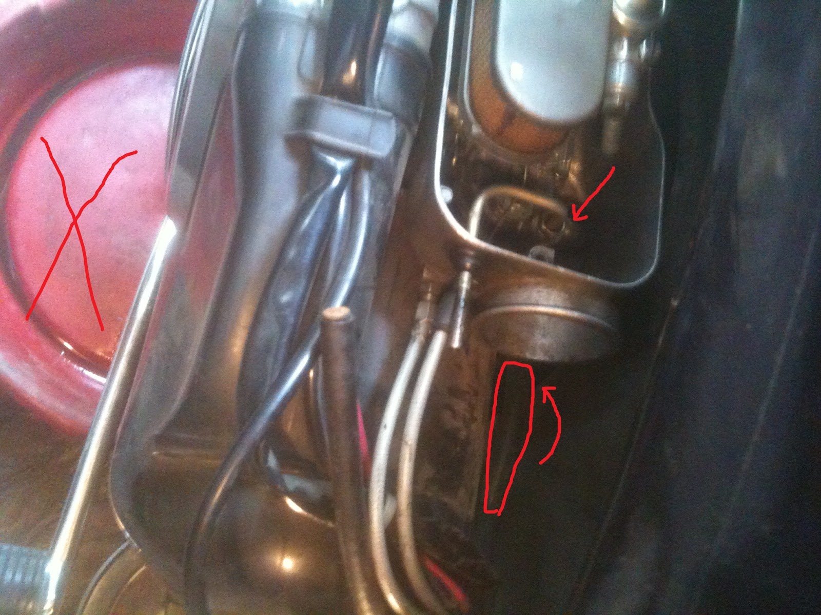
Once inside, you'll find the gas line, and oil line (if you run with oil injection).

Make sure your fuel shut-off is closed. Put a dish or something under your bike. You're likely to spill a little gas that's in the hose. Slide the clamps down, and disconnect the two hoses. I've indicated where I stuffed a nail in the oil line to plug it. I don't bother plugging the fuel line, since the fuel shutoff is closed.

Next, remove the air bellows. Note, I always find this a total bitch to install on the right hand side. I'm getting better at it, but it's a pain. Take a good look at it, nice and installed in there, then just tug it out.

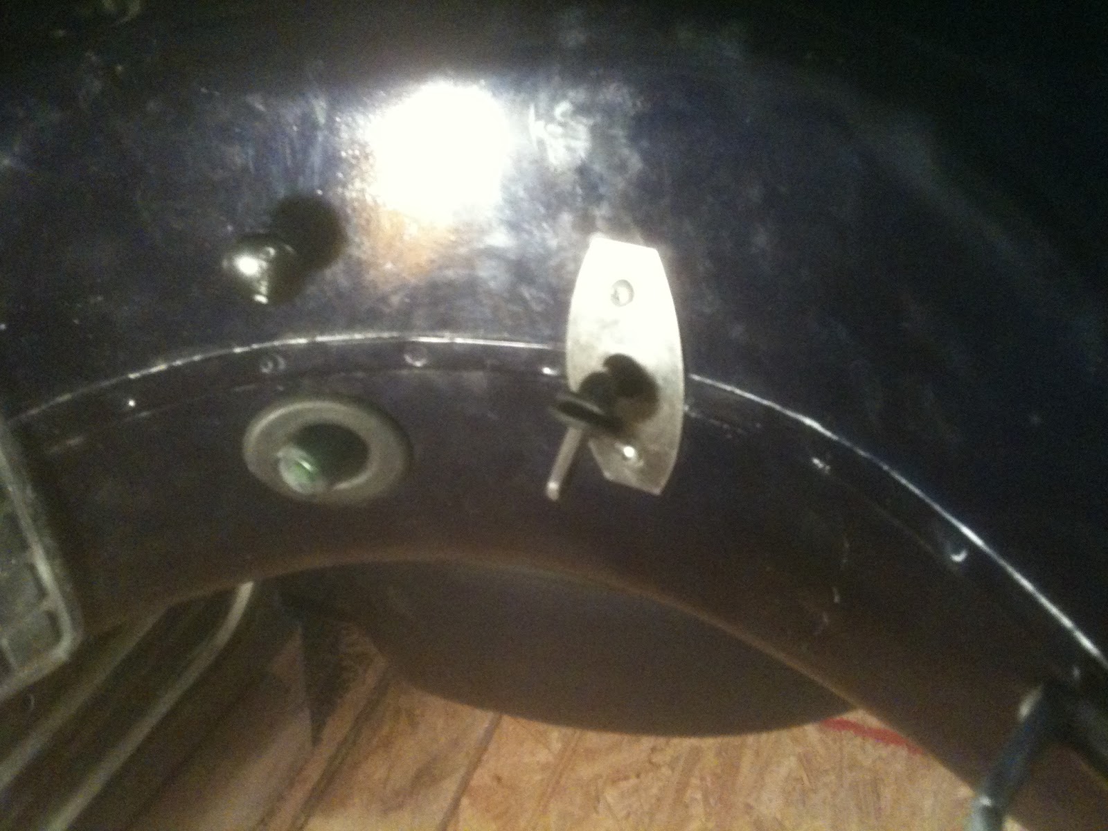
OK, now it's time to release the fuel shutoff lever. Remove the two screws in the plate.

Now, wrestle the grommet out of there, and remove the plate. I accidentally tore my grommet. If it feels stiff, you might try smearing some grease or vaseline on it to help get it off without destroying it.

Now, it's time to pull the fuel hose out the bottom of the air box. I put a red catch bin under the bike to get the gas that was left in the hose. It was probably less than 1/4 cup. I pointed the hose downward to get the fuel out of it.
We're almost there. I didn't take a picture, but here's the next thing I did. I wiped off the fuel and oil lines, removing the dirt and grit on them, and then slathered them with a thin layer of engine grease, so that they would go through the grommets more easily. I slid them in and out a bit, to start the grease into the grommets. Then I pushed them in a bit, to give me some slack inside the bike.
Once that was done, I began lifting the tank. Begin in the back, tipping the tank upward. The fuel petcock and sight glass will pull backward into their holes. Once they're clear, you can begin lifting on the front. In this picture, I hoisted the tank up enough to reach under it, and grab the fuel and oil lines. I pulled them through the grommets, and lifted them out so that they wouldn't dribble under the seat area.

Note, there's a gasket there too. Keep it with the tank. Since it's such an ungainly thing, and I had foolishly gassed up just before I started the project, I had nearly 2 gallons of gas in the tank. I decided to store it upright. I set up my workmate just outside my work shed, and set the tank aside, like so:

OK, the tank is out, so let's look down in there. You can see the plastic dust cover down in the bottom. It needs to come out to give you access to the channel beneath. Pull up on the rear section, and it should pop upward. Note, ignore the red and green wires you see. You won't have those, they're the wires for my retro-fitted starter motor.

Now that it's out, you can see the wiring channel underneath. I suggest taking a picture here, while you're at it. There are few wires that you want to be aware of. The left and right rear turn signals attach down here, as well as their grounds. While I worked, I knocked off my right blinker wire. Fortunately, I caught it before I reassembled everything. Anyway, they're prone to falling off when you wiggle wires down here, so check them at reassembly time.

OK, now it's time to start fishing the wire through. Make sure you know which end remains in the headset, and which end needs to lead down to the temperature sensor in the back of the bike.

I took a length of 10g wire (the red in this picture), and pushed it down from the headset, and out the opening behind the the horn cover. I then secured the temp sensor wire, and pulled it through the openings behind the horn cover.

At this point, I tried to pull the wire all the way from here to the tank area. I had no luck. It kept binding up on the other wires and cables in the channel. I decided to pull out the brake pedal, so that I'd have a half-way point where I could get my hands on the fish wire. I removed the brake pedal. There are two 10mm nuts, and one bolt to undo. Note, I dropped the brake down, but did not pull the foot pedal through the frame. I just pulled the pedal housing down enough to get access to the wire channel above.

At this point, it was fairly easy to get the wire from behind the horn cover to the brake pedal opening.

From there, it very easy to get the wire under the tank, finally!

From there, it was a really tight fit through the grommet near the cylinder head. I already have one additional 10mm red cable going through there for my starter motor. I put some grease on the wires, and pushed my fish wire a few times to push the grease all the way through. I then pushed the sensor wire through the grommet, very carefully, so I wouldn't snap the wires off the connector.

At this point, go ahead and connect this extension wire at the back of the speedo, and take up the slack from the headset. Extra slack from both ends should be left in the wire channel below the tank.
It was almost time to put things together, but I checked everything under the tank, and sure 'nuff, I had knocked off my blinker wire.

OK, all fixed. Time to button up. I tucked the wires back in place, and restored the black dust cover. Arrange the wires, and push the front end down first. Get it snapped into position, and then push it down in the back.

Note, before lowering the tank back in, double check that the choke cable is seated properly. Yes, I goofed when I did this, and had to pull the tank again.
Next, lower the tank into position. As you get it over the opening, push the fuel and oil lines back through the grommets. Line up the fuel petcock and guide it into the hole. Note, that as I did so, the grommet on the sight glass popped out. That's OK. It's not too hard to put back on. Keep tugging more and more slack out of the lines, as you get the tank into position.

Next replace the (2) 13mm bolts and acorn nut holding the tank in position. Make sure to line up the gasket under the tank properly, so that the bolts will pass through.

Then, go ahead and reinstall the seat with (3) 13mm bolts. I had two short and one long. I put the long in front.
(not pictured)
I put the trim plate back around the fuel petcock and stuffed the grommet back in there. Note, the grommet is very prone to tearing (yes, another oops). Lubricate it as best you can as you try to stuff it in place.
Now it's time to get the fuel line back into the airbox. I always found this to be a pain, as I couldn't manage to get the hose lined up with the grommet on the bottom of the airbox. I found this trick, which made it a lot easier. I lower a narrow phillips screwdriver down from the airbox, and then thread the fuel line onto it from below.

Then, I draw the screwdriver back out with the hose on it. The screwdriver helps align the hose so that it doesn't fold over, and stays rigid enough to pass through easily.


Now, put the air bellows back in place. I find it easiest to do the front first. I hook the lower, deepest part of the bellow around the lip, and then pull it snug around to the front. I use a flat-bladed screwdriver to help pull it onto the lip. It's pretty tricky to get on there on the first few tries, but it gets easier with practice (and I've had some). After you get the front on, go ahead and pull it around the airbox.

Now, go ahead and reinstall the brake pedal (2 nuts and a bolt). Do make sure that the wires for the brake light switch didn't pop off while you were working.
To reinstall the horn cover, first put the wires back on the horn (if you completely removed it), and then secure it with the two screws on the front of the bike first (behind the Piaggio trim). I find it easiest to do those two screws first, so that the screws you need to install from the glovebox are lined up already. Next, go ahead and do the two in the glovebox, and then finally, the one screw to reinstall the Piaggio trim piece.
Next, we install the temperature sensor. Screw the short "dongle" wire onto one of the red sensors, and then remove the spark plug, and place it in position. Very carefully, lower the plug back into position, and screw it in by hand, until you're confident it's lined up properly. The sensor makes it a little trickier to get the plug installed, so be very careful not to cross-thread it.

Once it's in place, plug the dongle wire into the extension wire you fished from the front of the bike. Here's how mine came out.

OK, now it's time to install the little button to operate the speedo. Unfortunately, mine wasn't convenient to install where the German video recommended. I had installed a starter button for my bike, so putting the speedo button below that would have been a little goofy. The wire to the button would not have sat flush against the handle.

If you have a stock setup on your p200, you'll probably want to install the button here. You can use the notch for the Run switch, and won't have to cut anything. That wasn't an option for me, so I elected to install it on the other handlebar. In order to do so, I needed to make a notch in the cover. Here's a notch I made with my dremel tool.

My High Beam/Horn switch had a big ugly hole in it, which was perfect for running the button cable through. I can't imagine the thing came this way, so some previous owner must have been up to something.
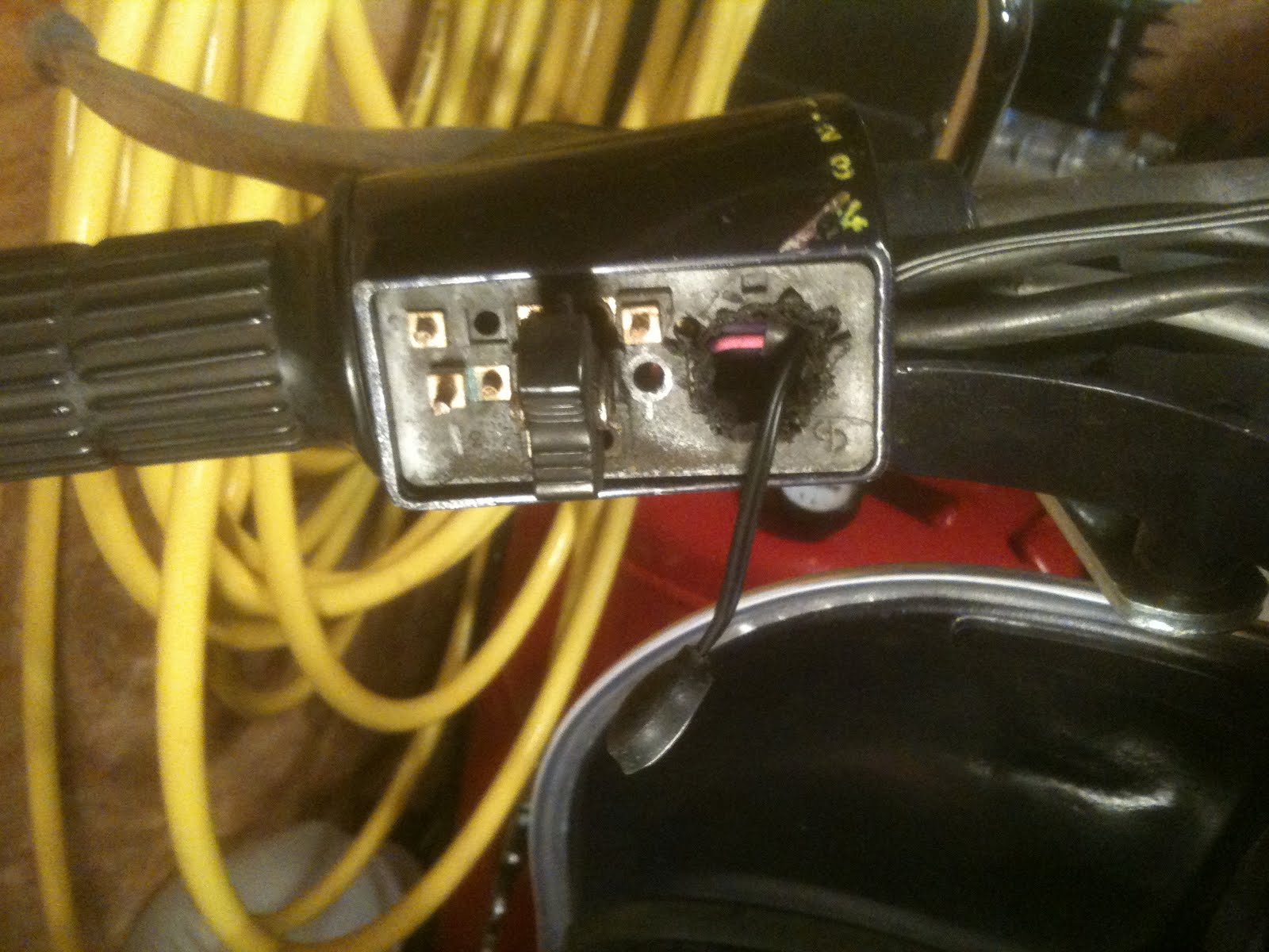
I reinstalled the cover, with the wire threaded through, and used the self-adhesive on the button to glue it to the bottom of the handlebar. Then, go ahead and plug the wire for the button into the back of the speedo.

Alright, so we've got two of the three wires we need to attach to the speedo squared away. We have the sensor wire from the back, and the wire from the switch button connected.

The last connector is for the RPM meter, and power. The installation manual is incorrect. It shows the red wire being connected directly to the battery. That's nonsense. The red wire turns on the speedo, including the backlight. It must be switched, or your battery would go dead.
The brown wire is the one used to pick up RPMs. Thought it's confusing in the manual,what they're trying to tell you is to hook it to an AC power source.
Now, as it happens, we have available all the things we need from the wires we removed from the old speedo. The neutral light gets power at all times when the ignition switch is on. The neutral switch actually connects the bulb to ground when activated. So, we can hijack the neutral switch wire and attach it to the red wire on the speedo.
The old speedo backlight is fed with AC power from the stator. Since the new speedo has it's own DC backlight, we can hijack the old speedo backlight wire for the RPM source.
Also, we disconnected a few black ground wires from the back of the old speedo. We'll hijack those, too.
Black: Ground
Red: Connect to white wires from Neutral light.
Brown:Connect to purple Speedo light wire.
Now, I hate those wiring clips provided with the speedo. I elected to make my own custom wiring harness.
The wiring harness for the power was immensely long. I cut it down to about 8 inches, and installed wire connectors as follows.
The white neutral light connect was a female connector, so I put a male connector on the red wire from the speedo.
The purple speedo backlight wire was also terminated with a female connector, so I put a male connector on the brown wire from the speedo.
The existing two ground wires were terminated with loop connectors. I installed a loop connector on the black wire from the new speedo as well. I used a small screw and nut to clip all three neutrals together.

I connected this modified dongle to the back of the speedo, and to the connectors in the headset. Note, the remaining brown wire attached to the neutral light. It's the ground wire coming from the neutral switch on the gear shift box. I just taped it off and left it in the headset.
The three ground wires were all nicely bolted together, but there are uninsulated hot leads inside the headset - notably, connecting to the ignition switch. I decided to tape up the grounds, just to make sure I didn't get a short.

OK, at this point it was all hooked up. I reinstalled the fuse, and did a quick test to make sure the speedo lit up. It was fine. At this point, I tested all the lights, brake switches and horn. I had a few wires work loose, which I quickly identified and corrected. One had popped off the brake switch harness in the headset, and two had fallen off the ignition switch a few times. It was easy to fix, using the information in the wiring diagram.
Once I confirmed all the electronics were working, I put the headset back into position over the speedo wire, and screwed the speedo cable into the new speedo.

At this point, we're all installed:

I used the button to go through the settings and set the clock. I started the bike and confirmed that the rev counter worked properly. There are a number of settings for the rev counter. I left the RPM setting on the default, and verified it was correct with my timing light's tach.
I left the speedo gear ratio setting at .75, the default. That was listed as appropriate for the p200e, and seems to work.
I did change the default tire circumference. It was set to 1000mm. I ran a measuring tape around my wheel, and multiplied the number of inches (52.25) by 25.4 to come up with 1327mm. I configured that on the speedo, and did a test run up the road. I drove 2 miles (by the GPS on my phone), and it matched exactly 2.0 miles on my speedo.
That's it! Best of luck with your installation!
Mike
Nice break down, Thank you very much
ReplyDeleteHi, great info above. Can you give a quick review? Would be really keen to hear if you've had any issues after the install as I'm thinking of getting one too. Thanks.
ReplyDeletePaul, I've got 8100 miles on the speedo, and it's working fine. The only issue I've had is replacing the CHT sensor dongle when my original cable broke due to my rough handling. SIP was out of stock for around 6 months. I finally found a domestic reseller with the part, but paid like $30 for the short dongle cable with the sensor. Ouch!
DeleteI'm MUCH more careful with it now! lol
All in all, I've been very satisfied with it. I'm seriously considering picking another one up for my spare bike.
Hojo
Do you still have your old P-series speedo. I need the odometer drum out of a junk speedo. Can you help?
Deletedanny.king@verizon.net
Hi Hojo, Thanks for the reply, looks like I'll be getting one soon. Bad luck about the sensor dongle. Paul.
ReplyDelete